Back with another Cyberdeck post!
Obsession Much?
I won’t argue with that… But because of its compact size, I can’t help but tinker and build more upon it!
A few (maybe alot) has changed. For one, the idea of using my ServerDeck as my go to has switched to using my Nix-Stick (new name change..). This change was due to easier package and environment control, which will be needed when I bring this to do some field testing. More will be explained later.
What Does It Look Like?
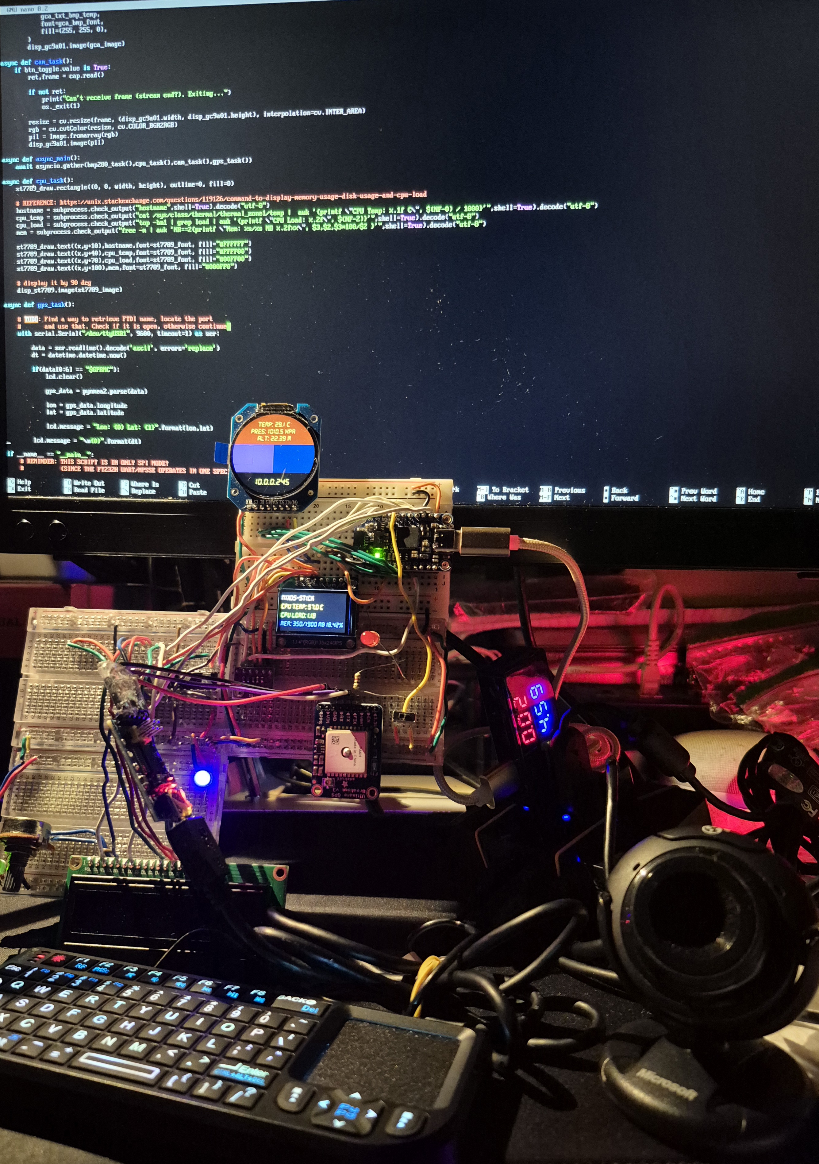
In Action
Yep, it’s a total mess… Let’s start breaking down what I have:
Hardware
Compute Stick setup:
- Wireless Mini Keyboard
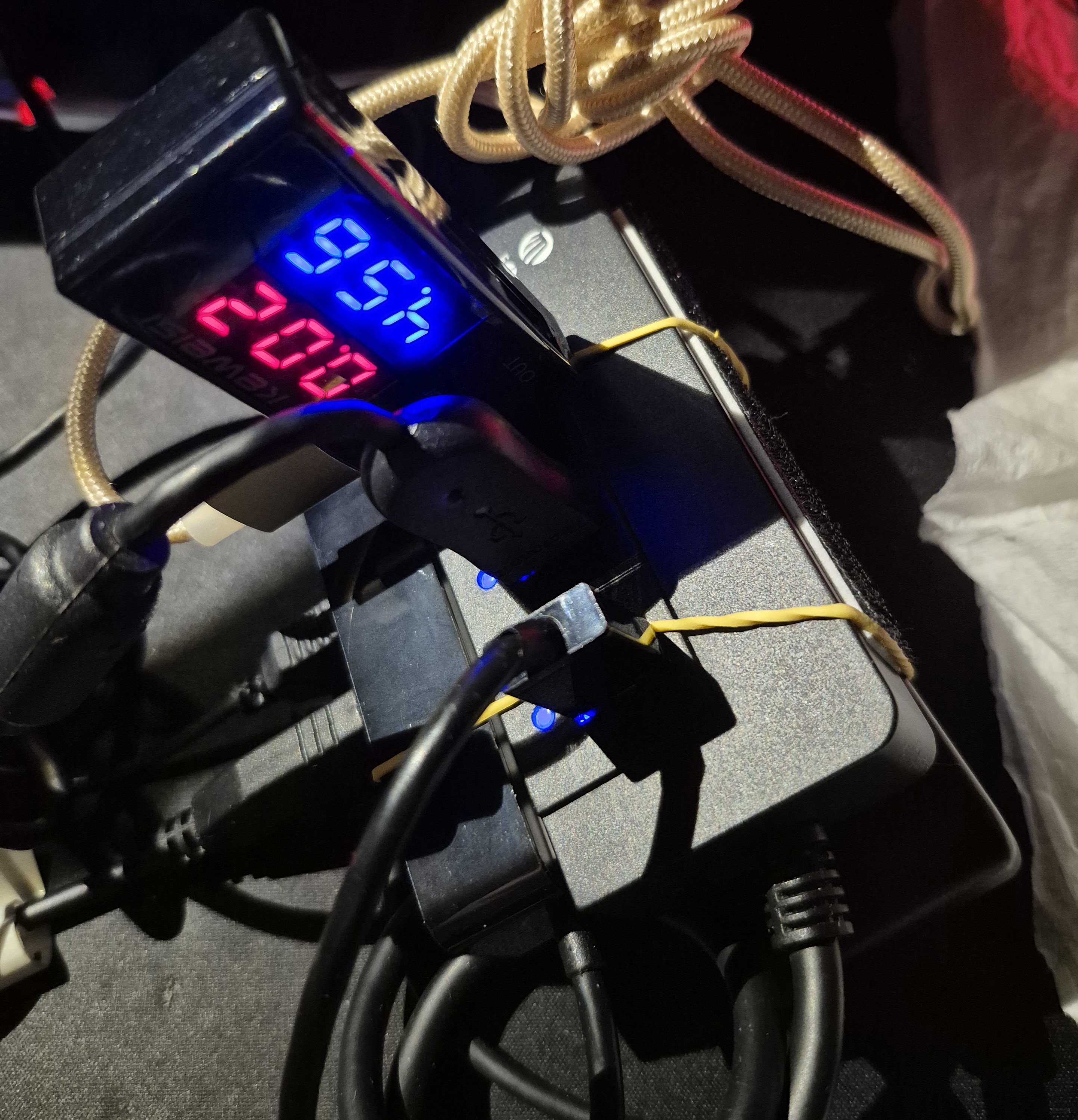
- USB Hub with Voltage & Current Tester
- AdaFruit FT232H (USB-C)
- FTDI FT232RL USB to TTL adapter
- USB Hubs:
Breadboard setup:
- Displays:
- GC9A01 (round display)
- ST7789 (square display)
- 16x2 LCD (rectangle display)
- BME280 (Barometric sensor)
- AdaFruit Ultimate GPS V3
- Shift Registers:
- 10K potentiometer
- Mini SPST Switch
Close up photo of the Nix-Stick:
Guess where the computer is!
Software
In a previous post when I was just focusing on my ServerDeck, I opted to use LibMPSSE that’s in C. I mentioned the documentation being a bit difficult to grasp and so this time I went with Adafruit_Blinka that’s written in Python. There’s alot of examples and tutorials from Adafruit themselves that it’s easier to get things tested!
What’s driving the whole circuit is the FT232H. Currently I am using the GC9A01 to display stats from the BME280, ST7789 is taking the computer’s: Hostname, CPU Temp, CPU Load, and Memory Usage. Finally the 16x2 LCD (potentiometer is used to adjust the backlight) is connected to the 74HC595 for extra outputs, showing longitude and latitude (datetime is separate) from AdaFruit Ultimate GPS V3, it is showing zeroes because you’ll have to be outside in order for it to work. I haven’t used the 74HC165 yet.
The mini SPST switch is used to switch over to start webcam streaming (OpenCV), a red LED is just for indication. The green and blue LEDs are to test if there’s voltage across connecting breadboards.
Here’s the code that drives this circuit:
main.py:
import board
from board import SCK, MOSI, MISO

import busio
import digitalio
from adafruit_rgb_display.st7789 import ST7789
from PIL import Image, ImageDraw, ImageFont

from adafruit_rgb_display.gc9a01a import GC9A01A

import adafruit_bmp280

import numpy as np
import cv2 as cv
import asyncio
import os

import time
import subprocess

import adafruit_character_lcd.character_lcd as character_lcd
import adafruit_74hc595

import wws_74hc165

import serial
import usb.core
import sys
import pynmea2
import datetime

spi = busio.SPI(clock=SCK, MOSI=MOSI, MISO=MISO)

def init_display(disp,cs,dc,reset,rotate,w,h,x_off,y_off,BAUDRATE=24000000):
    CS_PIN = cs
    DC_PIN = dc
    RESET_PIN = reset
    display = disp(
        spi,
        rotation=rotate,
        width=w,
        height=h,
        x_offset=x_off,
        y_offset=y_off,
        baudrate=BAUDRATE,
        cs=digitalio.DigitalInOut(CS_PIN),
        dc=digitalio.DigitalInOut(DC_PIN),
        rst=digitalio.DigitalInOut(RESET_PIN)
    )
    return display

def rotation(display):
    height=0
    width=0
    if display.rotation % 180 == 90:
        height = display.width  # swap height/width to rotate it to landscape
        width = display.height
    else:
        width = display.width  # swap height/width to rotate it to landscape
        height = display.height

    return height, width

def draw_image(disp,width,height,fill=0):
    disp.fill(0)
    disp_image = Image.new("RGB", (width,height))
    disp_draw = ImageDraw.Draw(disp_image)

    return disp_image, disp_draw

async def bmp280_task():
    if btn_toggle.value is False:
        gca_draw.rectangle((0, 0, disp_gc9a01.width, disp_gc9a01.height // 2 - 30), fill=(155, 50, 0))
        gca_txt_bmp_temp = "    Temp: {:.1f} C".format(bmp280.temperature) + "\nPres: {:.1f} hPa".format(bmp280.pressure) + "\n    Alt: {:.2f} M".format(bmp280.altitude)
        gca_draw.text(
            (disp_gc9a01.width // 2 - 70 , disp_gc9a01.height // 2 - 100),
            gca_txt_bmp_temp,
            font=gca_bmp_font,
            fill=(255, 255, 0),
        )
        disp_gc9a01.image(gca_image)

async def cam_task():
    if btn_toggle.value is True:
        ret,frame = cap.read()

        if not ret:
            print("Can't receive frame (stream end?). Exiting...")
            os._exit(1)

        resize = cv.resize(frame, (disp_gc9a01.width, disp_gc9a01.height), interpolation=cv.INTER_AREA)
        rgb = cv.cvtColor(resize, cv.COLOR_BGR2RGB)
        pil = Image.fromarray(rgb)
        disp_gc9a01.image(pil)

async def async_main():
    await asyncio.gather(bmp280_task(),cpu_task(),cam_task(),gps_task())

async def cpu_task():
    st7789_draw.rectangle((0, 0, width, height), outline=0, fill=0)

    # REFERENCE: https://unix.stackexchange.com/questions/119126/command-to-display-memory-usage-disk-usage-and-cpu-load
    hostname = subprocess.check_output("hostname",shell=True).decode("utf-8")
    cpu_temp = subprocess.check_output("cat /sys/class/thermal/thermal_zone1/temp |  awk '{printf \"CPU Temp: %.1f C\", $(NF-0) / 1000}'",shell=True).decode("utf-8")
    cpu_load = subprocess.check_output("top -bn1 | grep load | awk '{printf \"CPU Load: %.2f\", $(NF-2)}'",shell=True).decode("utf-8")
    mem = subprocess.check_output("free -m | awk 'NR==2{printf \"Mem: %s/%s MB %.2f%%\", $3,$2,$3*100/$2 }'",shell=True).decode("utf-8")

    st7789_draw.text((x,y+10),hostname,font=st7789_font, fill="#FFFFFF")
    st7789_draw.text((x,y+40),cpu_temp,font=st7789_font, fill="#FFFF00")
    st7789_draw.text((x,y+70),cpu_load,font=st7789_font, fill="#00FF00")
    st7789_draw.text((x,y+100),mem,font=st7789_font, fill="#000FF0")

    # display it by 90 deg
    disp_st7789.image(st7789_image)

async def gps_task():

    # TODO: Find a way to retrieve FTDI name, locate the port
    #       and use that. Check if it is open, otherwise continue
    with serial.Serial("/dev/ttyUSB1", 9600, timeout=1) as ser:

        data = ser.readline().decode('ascii', errors='replace')
        dt = datetime.datetime.now().strftime("%Y/%m/%d %H:%M")

        if(data[0:6] == "$GPRMC"):
            lcd.clear()

            gps_data = pynmea2.parse(data)

            lon = gps_data.longitude
            lat = gps_data.latitude

            lcd.message = "Lon:{0} Lat:{1}".format(lon,lat)
            print(lcd.message)

        lcd.message = "\n{0}".format(dt)

if __name__ == "__main__":
    # REMINDER: THIS SCRIPT IS IN ONLY SPI MODE!
    #           (SINCE THE FT232H UART/MPSSE OPERATES IN ONE SPECIFIC MODE)

    # -----74HC165 IS INPUT ONLY-----
    _74hc165_isr_latch = board.D5
    _74hc165_isr = wws_74hc165.ShiftRegister74HC165(spi, _74hc165_isr_latch, 1)

    # -----74HC595 IS OUTPUT ONLY-----
    _74hc595_isr_latch = digitalio.DigitalInOut(board.D6)
    _74hc595_isr = adafruit_74hc595.ShiftRegister74HC595(spi, _74hc595_isr_latch, 1)

    # connecting LCD to 74HC595
    lcd_rs = _74hc595_isr.get_pin(0)
    lcd_en = _74hc595_isr.get_pin(1)
    lcd_d7 = _74hc595_isr.get_pin(2)
    lcd_d6 = _74hc595_isr.get_pin(3)
    lcd_d5 = _74hc595_isr.get_pin(4)
    lcd_d4 = _74hc595_isr.get_pin(5)

    lcd_backlight = _74hc595_isr.get_pin(6)

    lcd_columns = 16
    lcd_rows = 2

    lcd = character_lcd.Character_LCD_Mono(lcd_rs, lcd_en, lcd_d4, lcd_d5, lcd_d6, lcd_d7, lcd_columns, lcd_rows, lcd_backlight)
    lcd_backlight.value = True
    lcd.message = "BOOTING\nUP..."

    # clear old outputs for incoming ones
    subprocess.run(["clear"])

    # switch for camera mode for round display
    btn_toggle = digitalio.DigitalInOut(board.D4)
    btn_toggle.direction = digitalio.Direction.INPUT

    # list connected USB devices
    print("ls /dev/video* : ",subprocess.check_output("ls /dev/video* | grep -oP '/dev/video\d+' | tr '\n' ' ' | sed 's/ $//'",shell=True))
    print("ls /dev/ttyUSB* : ",subprocess.check_output("ls /dev/ttyUSB* | grep -oP '/dev/ttyUSB\d+' | tr '\n' ' ' | sed 's/ $//'",shell=True))

    # camera check
    cap = cv.VideoCapture(-1)
    if not cap.isOpened():
        print("Cannot open camera...")
    cap.set(cv.CAP_PROP_FPS,30)

    # barometer setup for round display
    bmp280 = adafruit_bmp280.Adafruit_BMP280_SPI(spi, digitalio.DigitalInOut(board.C7))
    gca_bmp_font = ImageFont.truetype('./DS-DIGIT.TTF',20)

    # ----------------set up round display ----------------
    disp_gc9a01 = init_display(GC9A01A,board.C6,board.C5,board.C4,180,240,240,0,0)
    gca_image, gca_draw = draw_image(disp_gc9a01,disp_gc9a01.width,disp_gc9a01.height)

    gca_draw.rectangle((0, 0, disp_gc9a01.width, disp_gc9a01.height // 2 - 30), fill=(155, 50, 0))                          # upper rectangle
    gca_draw.rectangle((0, 90, disp_gc9a01.width // 2, disp_gc9a01.height // 10 + 150), fill=(105, 50, 150))                # left rectangle
    gca_draw.rectangle((120, 90, disp_gc9a01.width // 2 + 150, disp_gc9a01.height // 10 + 150), fill=(10, 50, 100))         # right rectangle

    gca_font = ImageFont.truetype('./DS-DIGIT.TTF',25)
    gca_txt_ip = subprocess.check_output("ip -4 addr | grep -oP '(?<=inet\s)\d+(\.\d+){3}' | grep -v '127\.0\.0\.1'",shell=True).decode("utf-8")
    gca_draw.text(
        (disp_gc9a01.width // 2 - 50 , disp_gc9a01.height // 2 + 70),
        gca_txt_ip,
        font=gca_font,
        fill=(255, 255, 0),
    )
    disp_gc9a01.image(gca_image)
    # ------------------------------------------------------


    # ---------------- set up tft display ----------------
    x = 0
    y = -2
    disp_st7789 = init_display(ST7789,board.C3,board.C2,board.C1,90,135,240,53,40)
    height,width = rotation(disp_st7789)
    st7789_image, st7789_draw = draw_image(disp_st7789,width,height)
    st7789_font = ImageFont.truetype('./DS-DIGIT.TTF',23)
    # ------------------------------------------------------

    lcd.clear()

    # gracefully exit when CTRL+C
    try:
        while True:
            asyncio.run(async_main())

    # offload camera, lcd, and exit
    except KeyboardInterrupt:
        cap.release()
        lcd.clear()
        lcd.backlight = False
        os._exit(1)
        print("\nCancelled...")
Of Course There’s Trouble…
There is a forum discussing how difficult it is to use Python in NixOS due to the way how regular Linux Distro’s link C++ .so files. Luckily there was a script I found in the GitHub documentation that I modified for my needs:
default.nix
with import <nixpkgs> { };

let
  pythonPackages = python3Packages;
in pkgs.mkShell rec {
  name = "impurePythonEnv";
  venvDir = "./.venv";
  buildInputs = [
    # A Python interpreter including the 'venv' module is required to bootstrap
    # the environment.
    pythonPackages.python

    # This execute some shell code to initialize a venv in $venvDir before
    # dropping into the shell
    pythonPackages.venvShellHook

    # Those are dependencies that we would like to use from nixpkgs, which will
    # add them to PYTHONPATH and thus make them accessible from within the venv.
    pythonPackages.numpy
    pythonPackages.requests
    pythonPackages.pyftdi

    # In this particular example, in order to compile any binary extensions they may
    # require, the Python modules listed in the hypothetical requirements.txt need
    # the following packages to be installed locally:
    libusb1
   ];

  # Run this command, only after creating the virtual environment
#  postVenvCreation = ''
#    unset SOURCE_DATE_EPOCH
#    pip install -r requirements.txt
#  '';

 packages = [ pkgs.screen ];

# For linking OpenCV libraries
 LD_LIBRARY_PATH = lib.makeLibraryPath [ pkgs.stdenv.cc.cc ];

 shellHook = ''
   alias c="clear"
   alias h="history -c"
   alias la="ls -la"

   source .venv/bin/activate
   which python3
   python3 sanity_test.py
  # python3 blink_test.py
   ls /dev/ttyUSB*
   ls /dev/video*
 '';


  # Now we can execute any commands within the virtual environment.
  # This is optional and can be left out to run pip manually.
  postShellHook = ''
    # allow pip to install wheels
    unset SOURCE_DATE_EPOCH
    BLINKA_FT232H=1
  '';

}
Since this environment relies on the PIP package, the following is the libraries I’ve used:
requirements.txt
Adafruit-Blinka==8.56.0
adafruit-blinka-displayio==2.1.7
adafruit-circuitpython-74hc595==1.4.6
adafruit-circuitpython-bitmap_font==2.2.0
adafruit-circuitpython-bmp280==3.3.6
adafruit-circuitpython-busdevice==5.2.11
adafruit-circuitpython-charlcd==3.5.1
adafruit-circuitpython-connectionmanager==3.1.3
adafruit-circuitpython-framebuf==1.6.7
adafruit-circuitpython-mcp230xx==2.5.16
adafruit-circuitpython-register==1.10.2
adafruit-circuitpython-requests==4.1.10
adafruit-circuitpython-rgb-display==3.13
adafruit-circuitpython-ticks==1.1.2
adafruit-circuitpython-typing==1.11.2
Adafruit-PlatformDetect==3.77.0
Adafruit-PureIO==1.1.11
binho-host-adapter==0.1.6
brotlicffi==1.1.0.0
certifi==2024.8.30
cffi==1.17.1
charset-normalizer==3.3.2
idna==3.10
numpy==1.26.4
opencv-python-headless==4.11.0.86
pillow==11.1.0
pycparser==2.22
pyftdi==0.55.4
pynmea2==1.19.0
pyserial==3.5
pyusb==1.2.1
requests==2.32.3
sysv_ipc==1.1.0
typing_extensions==4.12.2
urllib3==2.2.3
woolseyworkshop-circuitpython-74hc165==1.0.0
Wait, What About Your ServerDeck?
Don’t worry, it’s still up and running! I probably might use this to handle whatever incoming data Nix-Stick is processing through the USBs Ethernet adapter like I had before.
So What Now?
Hmm…. More prototyping? Get this outside? There’s plenty of things to do with this Compute Stick and frankly I am suprised it’s able to handle a lot.