That breadboard setup is finally gone!
I finally toke the time from my previous build to solder everything together.
I have been thinking for a while about how to keep my build compact, at first I just wanted to do the same old… Use a decent size protoboard and assemble them! But it didn’t feel right, the whole idea of a cyberdeck was its portability.
So I decided to make it stackable. But how? I was afraid of cramming electronics together and potentially breaking things, and in turn that would be difficult to troubleshoot (I learned that the hard way…). After a few brainstorming sessions, I came up with the following:
First Layer
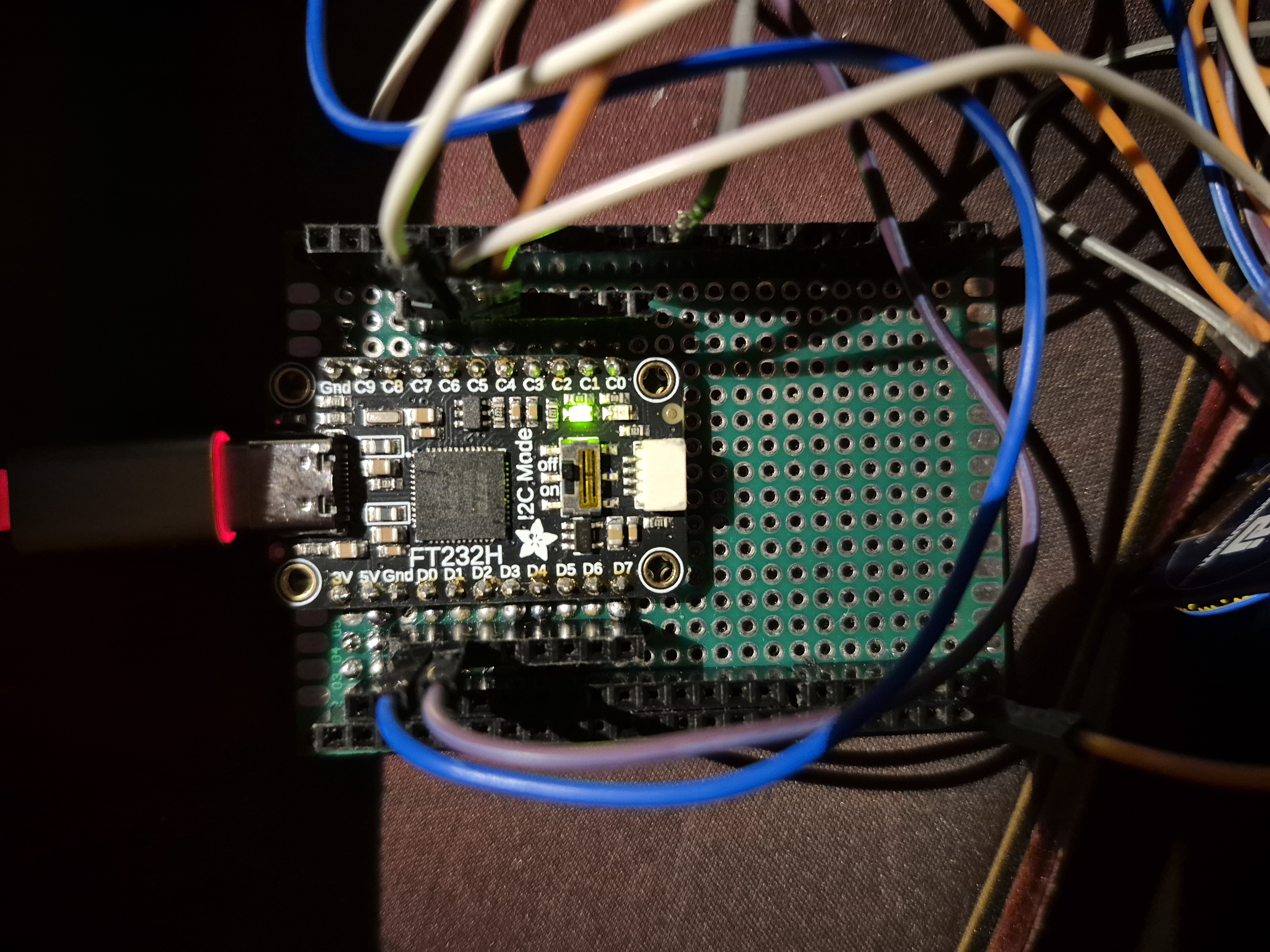
This will only house the FT232H and provide pins as well as 5V, 3.3V, and GND rails. The left shows VCC and right is GND
Second Layer
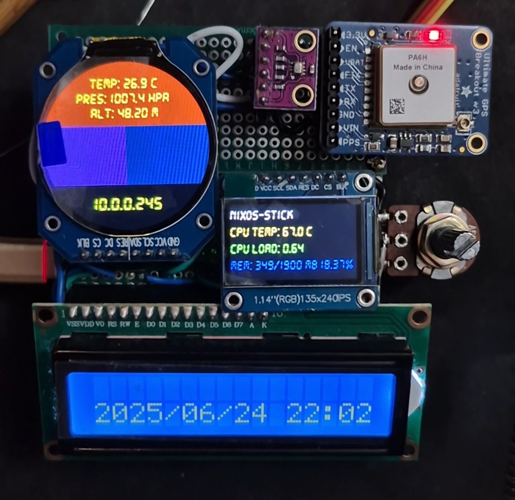
Here’s where all of my displays and sensors are “snuggly” placed onto. Where the BMP280 and GPS are placed is actually another protoboard held together with two screws and a rubber band!
There was this strange issue where the I intialized C7 as the CS pin of the BMP280 at one point stopped working. I kept getting errors where the chip gets unrecognized, the values I got were 0x0 and 0x20. I solved this by switching to D7, I have yet to figure out why that is….
Setup
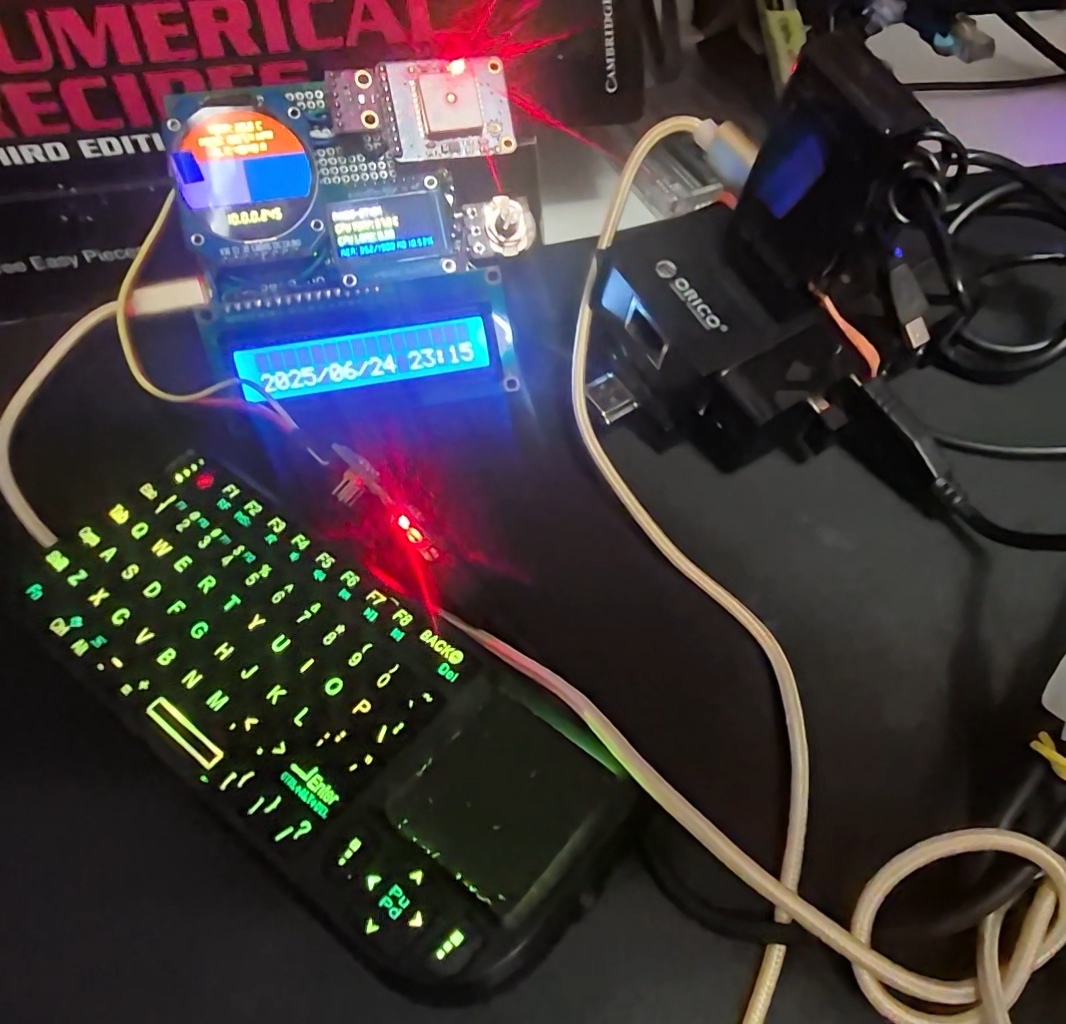
Looks a bit better, right??
Schematic
It’s funny how I long I breadboard prototyped but didn’t bother to draw the schematic until later. But here it is now!
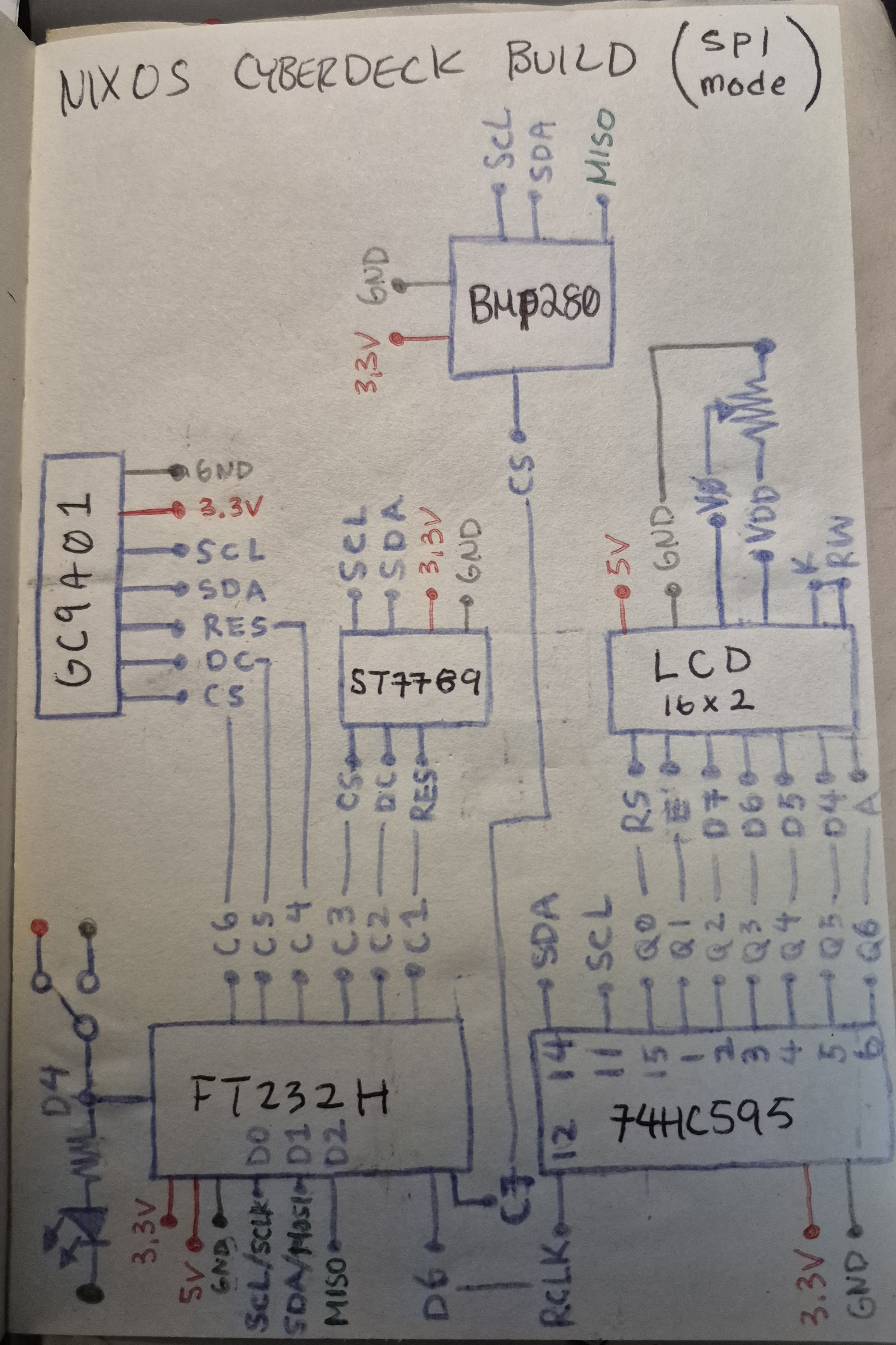
D4 is was suppose to initialize the webcam I had. I felt it didn’t need to be there so I removed it.
Demo
What’s Next?
I have plans to field test this, just to make sure the GPS and barometric sensor is working as intended.